
Information
MMCX RF Connectors
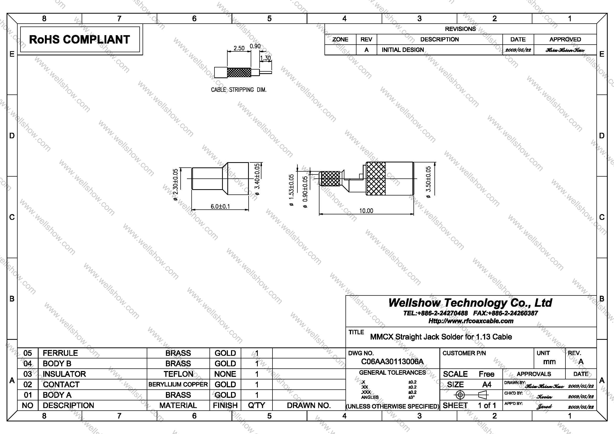
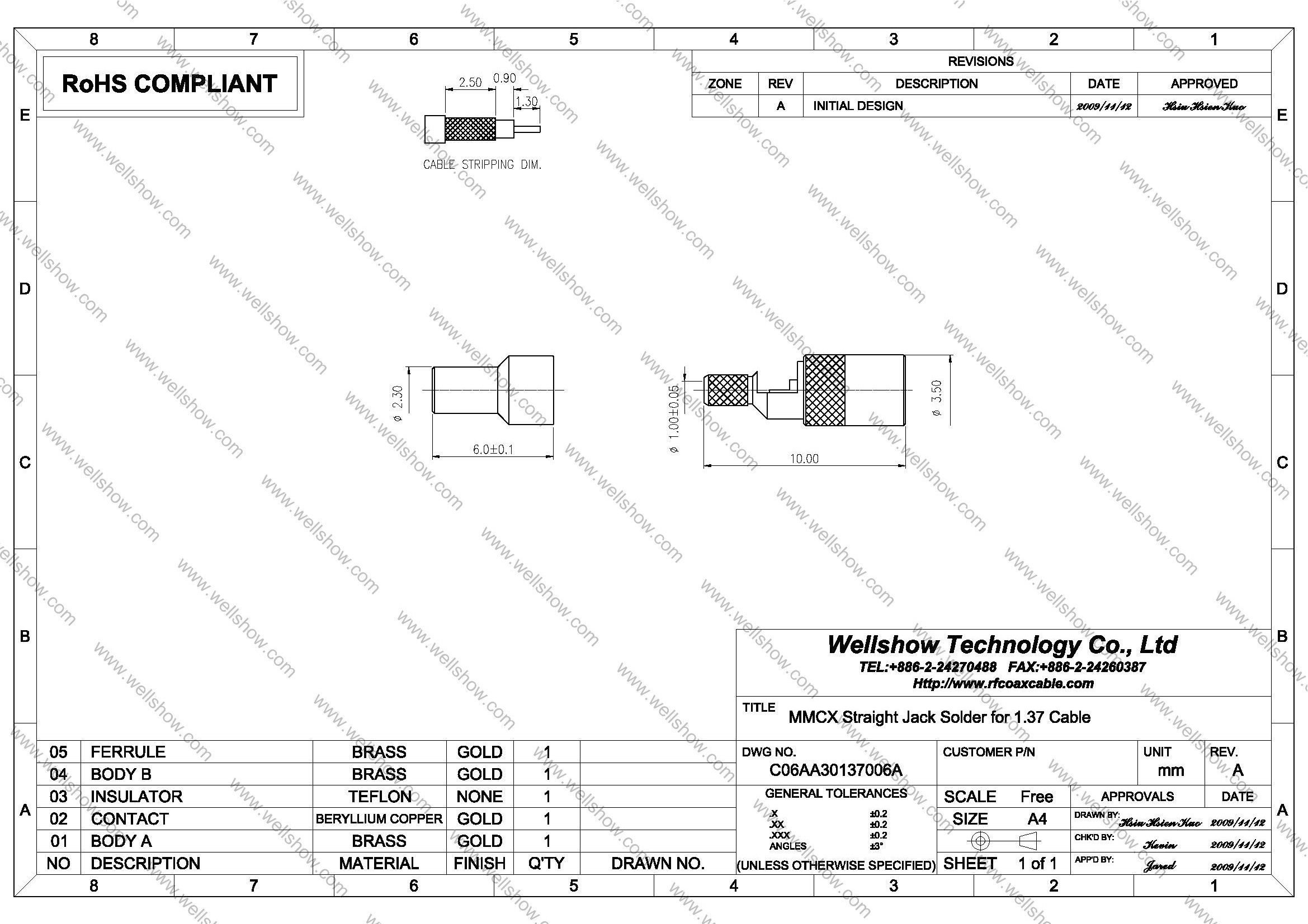
MMCX connector is one kind of RF connectors. This MMCX connector is jack/ female, and straight type. It’s designed to terminate with RF Coaxial Cables by crimping to be MMCX adaptor RF cable. The applicable RF coax cable is 1.37mm, 1.32mm and 1.13mm RF coaxial cable. Its plating is Gold over brass and the impedance is 50 ohm.
MMCX connector is small size in RF connector. MMCX Connector has snap-on coupling design. Besides, MMCX jack crimp series still have Right angle jack , straight bulkhead crimp jack, PCB mount jack, edge mount jack and SMT jack . MMCX Connector commonly is used for 0~3GHz. If you need higher working frequency, special mechanical design, customized RF connector, or RF cables, please contact us.
MMCX connector jack straight crimp type can be terminated with 1.13mm, 1.32mm and 1.37mm RF coaxial Cable to be RF Cable assembly and play the role to transmit RF Signal in Radio Frequency. MMCX RF connector is most commonly used in GPS Antenna, GSM Antenna or GPS/GSM application these kinds of RF connectors industry.
Part Numbers
| P/N | RF connector description | Cable Group | Ohm |
| C06AA30113006A C06AA30137006A | MMCX RF connector straight crimp jack MMCX RF connector straight crimp jack | 1.13 1.32, 1.37 | 50 50 |
Cable Assembly
Cable Assembly Instructions Crimp type


Specification
MMCX Connector Specification
| Electrical | |
| Impedance | 50 ohm |
| Frequency range | 0 ~ 6 GHz |
| VSWR | Straight type ≦ 1.3 max. |
| R/A type ≦ 1.5 max. | |
| Dielectric withstanding voltage | 500 V rms |
| Working voltage | 170 V rms |
| Center contact resistance | ≦ 5.0 mΩ (Milliohms max.) |
| Outer contact resistance | ≦ 2.5 mΩ (Milliohms max.) |
| Insulation resistance | ≧ 103 MΩ (Megohms min.) |
| Mechanical | |
| Coupling | Lock-snap |
| Contact Retention | 2.3 lbs min. |
| Mating Durability | 500 cycles min. (For Beryllium copper contact only) |
| Environmental | |
| Temperature Range | Teflon -65°C ~ +155°C |
| Vibration | MIL-STD-202 Meth. 204 |
| Corrosion resistance | MIL-STD-202 Meth. 101 |
| Materials | |
| Body, coupling nut | Brass |
| Insulator | Teflon |
| Center contact | Brass for male, |
| Beryllium copper for female | |
| Crimping sleeve | Annealed Brass |
| Body plating | Gold (Ag) |
| Center contact plating | Gold (Ag) |
Note: These characteristics are typical and may not apply to all connectors.


