
Information
SMA (SubMiniature version A) connectors are coaxial RF connectors developed in the 1960s for coaxial cable with thread mating. The SMA connector has 50 ohm impedance. It offers excellent electrical performance from DC to 18 GHz.
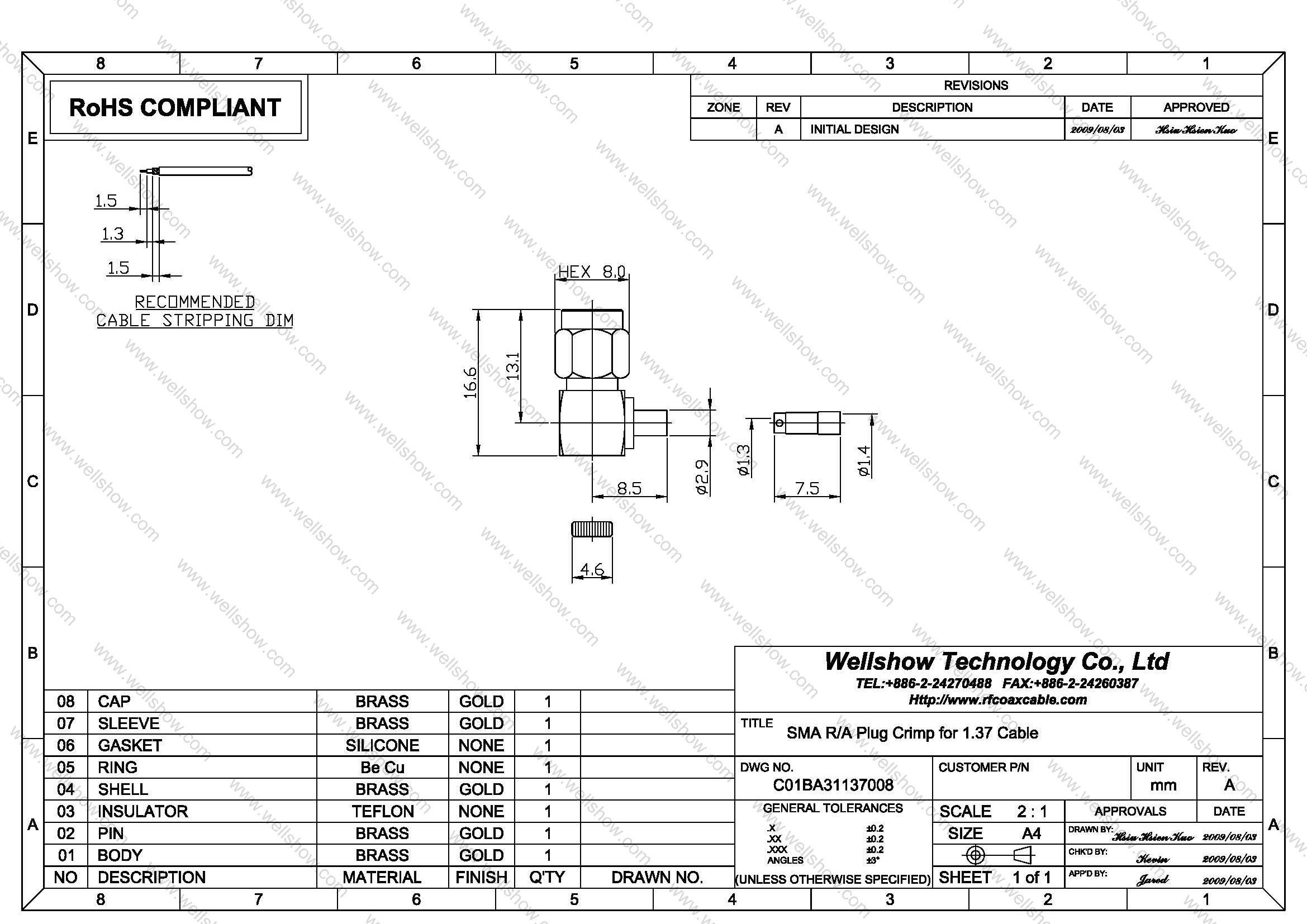
This SMA right angle plug can combine with RF coaxial cable from 0.81mm, 1.13mm, 1.32mm, 1.37mm, 1.48mm, to RG178. If you want to use SMA right angle plug to match with thicker RF cable than the above, please link here.
SMA male connector has the 8mm hex coupling nut. Because RF SMA Connectors are compact in size and have outstanding durability and high-performance, SMA male and SMA female are the most popular RF connector in various application.
Part Numbers
| P/N & Drawing | Description | Cable Group | Ohm |
|---|---|---|---|
| C01BA31081008 C01BA31113008 C01BA31132008 C01BA31137008 C01BA31148008 C01BA31178008 | SMA right angle crimp plug SMA right angle crimp plug SMA right angle crimp plug SMA right angle crimp plug SMA right angle crimp plug SMA right angle crimp plug | 0.81mm 1.13mm 1.32mm 1.37mm 1.48mm RG178 | 50 50 50 50 50 50 |
Cable Assembly
Cable assembly Instructions Crimp type
Step1. All parts of SMA RF connector are shown as the top line.
Step2. Strip the RF coaxial cable into center conductor, insulator, shielding three parts per recommended stripping dimension shown in SMA RF connector spec.
Step3. Slide the heat shrinking tube on cable jacket, ferrule on cable braid, spacer onto cable dielectric.
Step4. Insert the center conductor into the pin’s slot and solder it, and then push the other parts into main body until it stops.
Step5. Proceed the first open-short test to make sure signal can transmit well.
Step6. Place the insulator then cap on, and press cap into main body.
Step7. Heat shrink the shrinking tube.
Step8. Do the open-short test of every cable assembly before QC examination.
Specification
SMA Connector Technical Characteristics
| Electrical | |
| Impedance | 50 ohm |
| Frequency range | 0 ~ 18 GHz |
| VSWR | Straight type ≤ 1.3 max. |
| R/A type ≤ 1.5 max. | |
| Dielectric withstanding voltage | 1000 V rms min. for RG142, RG405 750 V rms min. for RG316, RG402 500 V rms min. for RG178 |
| Working voltage | 500 V rms max. for RG142, RG405 375 V rms max. for RG316, RG402 170 V rms max. for RG178 |
| Center contact resistance | ≤ 6.0 mΩ (Milliohms max.) |
| Outer contact resistance | ≤ 2.0 mΩ (Milliohms max.) |
| Insulation resistance | ≥ 5×10³ MΩ (Megohms min.) |
| Mechanical | |
| Coupling | 1/4-36 thread |
| Contact Retention | 15 in-lbs. min. |
| Mating torque | 2 in-lbs. min. |
| Mating Durability | 500 cycles min. (For Beryllium copper contact only) |
| Environmental | |
| Temperature Range | −65ºC ~ +155 ºC |
| Vibration | MIL-STD-202 Meth. 204 |
| Corrosion resistance | MIL-STD-202 Meth. 101 |
| Materials | |
| Body, coupling nut | Brass, Non-magnetic stainless steel |
| Insulator | Teflon |
| Center contact | Brass for male, Beryllium copper for female |
| Crimping sleeve | Annealed Brass |
| Body plating | Nickel (Ni), Gold (Au), Passivated |
| Center contact plating | Gold (Au) |
Note: These characteristics are typical and may not apply to all connectors.


