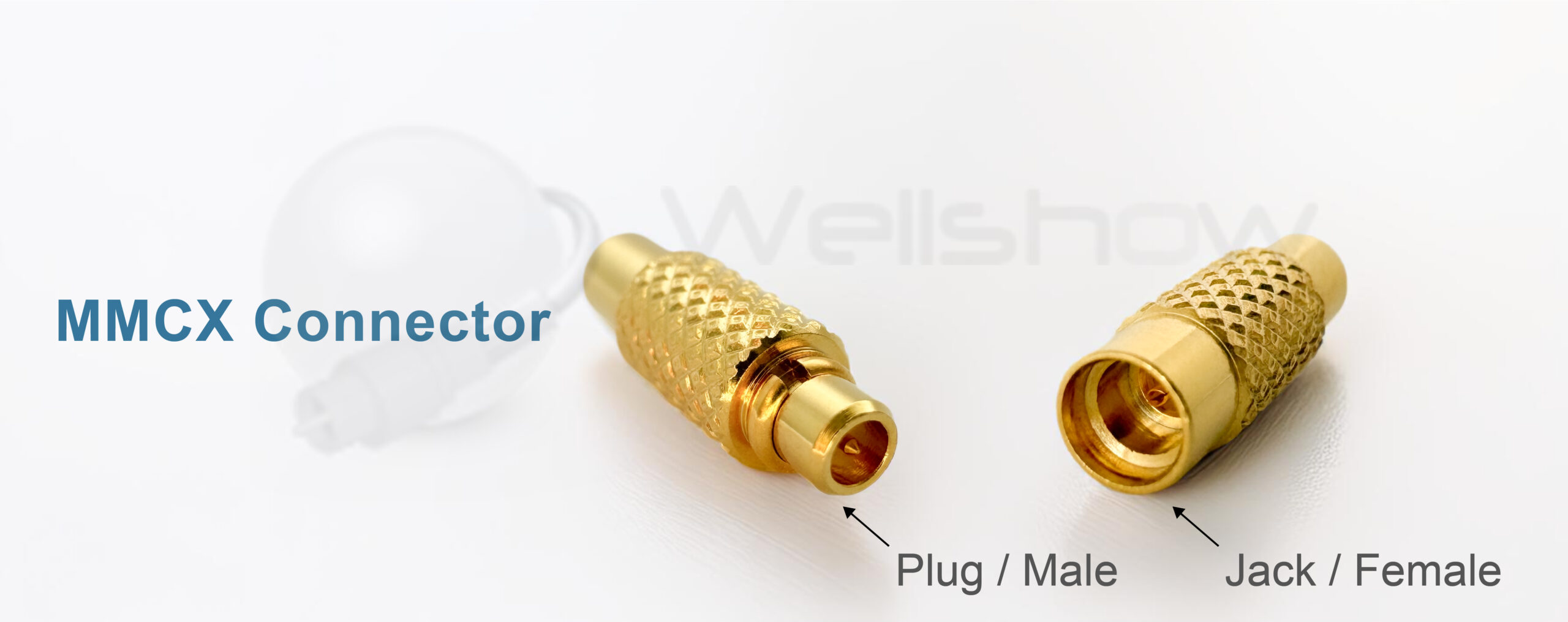
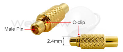
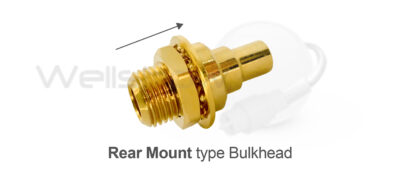
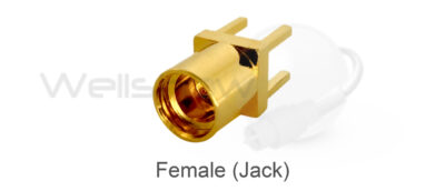
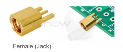
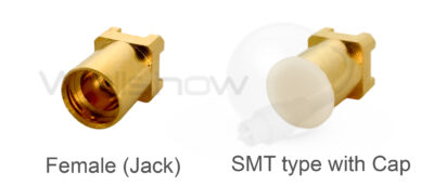
The MMCX connector is smaller than the MCX connector and was designed in the 1990s with a lock-snap mechanism. The snap-on design allows users to connect and disconnect the MMCX connector rapidly in limited spaces.

The MMCX connector has a 50-ohm impedance and is usually specified for frequencies up to 6GHz. The lock-snap mechanism design allows MMCX connectors to be rotated 360 degrees.

The MMCX connector is used in many different applications such as GPS tracking, GSM cellular, Wi-Fi, and WLAN equipment.

Mechanical Feature:

MMCX plug(male)

  1. Snap-on coupling.
  2. C-clip on MMCX plug(male) for mating captive.
  3. Outer diameter is 2.4mm max.
  4. Plug(Male) center contact.

MMCX jack(female)

  1. Snap-on coupling.
  2. Inner diameter is 2.41 min. for mating.
  3. Jack(Female) center contact.
  4. Part of the jack(female) contact is not surrounded by the insulator.

How to judge MMCX connectors’ feature from outline:

The diameter of the MMCX plug(male) connector is about 2.4mm, and there is a C-clip for the lock-snap mechanism with the MMCX jack(female) connector.

The inner diameter of the MMCX jack(female) connector is about 2.41mm. There is no insulator surrounding the MMCX jack(female) center contact.

The cable entry or PCB termination is at 90 degrees to the coupling direction.

The cable entry or PCB termination is at 180 degrees to the coupling direction.

Besides the mating trough, there is an outer thread on the body, which defines this SMB connector as a bulkhead type.

Rear mount type bulkhead
The MMCX connector bulkhead type will go through the panel mounting hole from the inside of the device to the outside and is mounted with a washer and nut from the outside.

PCB type MMCX connectors normally have leg lengths of 3.0. Four legs and one conductor go through the PCB vertically and are soldered on the rear side of the PCB.

An MMCX edge mount type connector will be mounted on the PCB from the board's edge.

SMT (Surface Mount Technology) type MMCX connectors have short legs 0.6mm. These legs and the conductor will be mounted directly on the surface of the PCB.