
Information
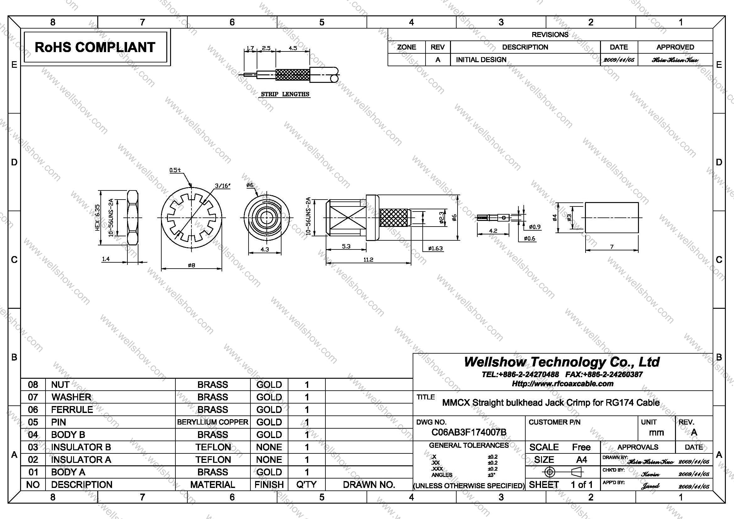
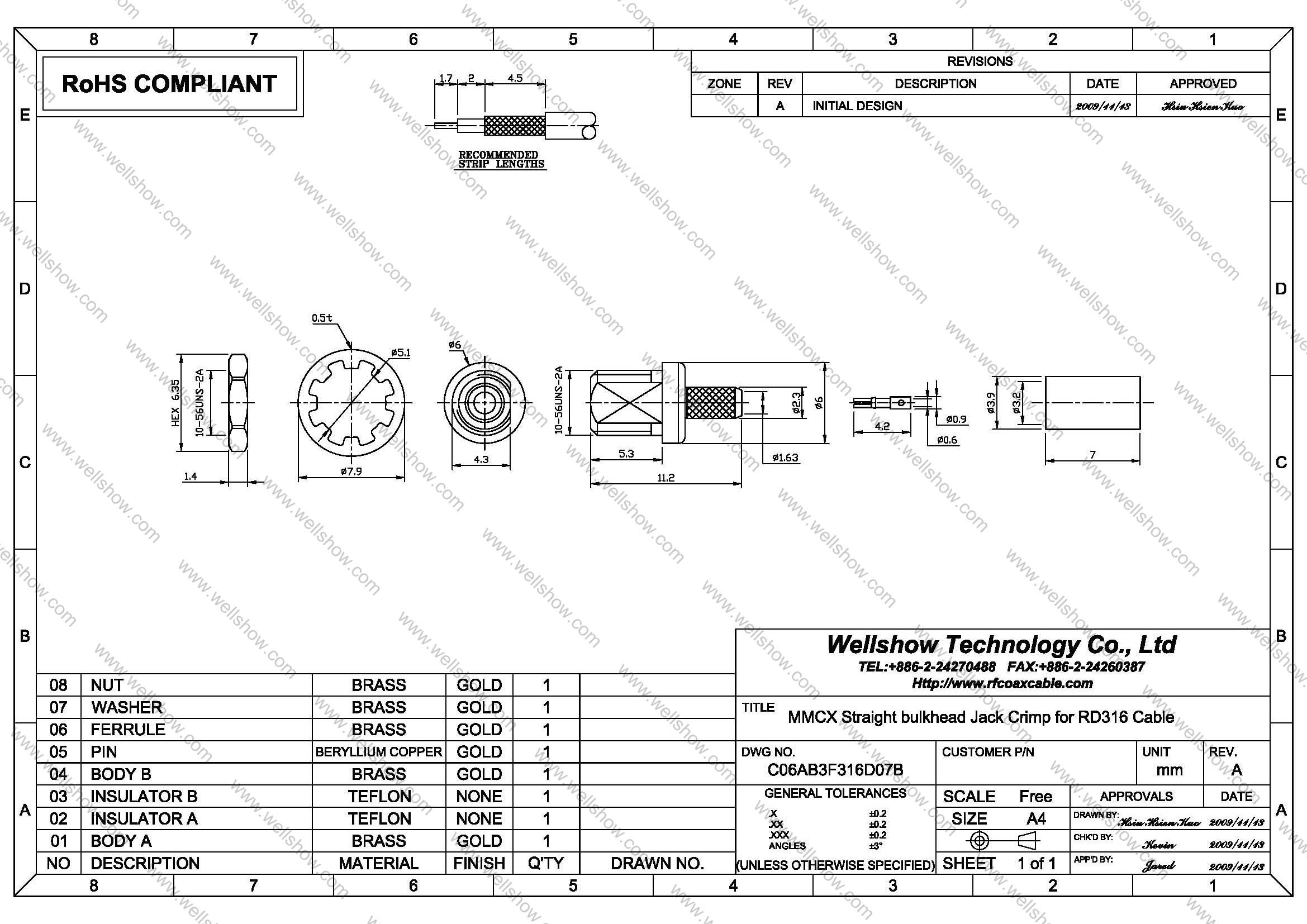
MMCX connector is one series of RF connectors. This MMCX connector is jack/ female, and straight bulkhead type. This MMCX jack bulkhead type will be terminated with RF Coax Cable to be MMCX cable assembly for signal transmitting. The applicable RF coax cable is RG174/ RG316/ RG178/ LMR100/RD316/RG188 RF coaxial cable. Its plating is Gold over brass and the impedance is 50 ohm.
MMCX connector is kind of small in RF connector. MMCX Connectors have snap-on mechanical mating design. Besides, MMCX jack crimp series still have Right angle jack , straight crimp jack, PCB mount jack, edge mount jack and SMT jack. MMCX Connector commonly is used for 0~3GHz. If you need higher working frequency, special mechanical design, customized RF connector, or RF cables, please contact us.
MMCX connector jack straight bulkhead crimp type can be terminated with RG174/ RG316/ RG178/ LMR100/RD316/RG188/RG196 RF coaxial Cable to be RF Cable assembly. It can transmit RF Signal well in various telecommunications. MMCX RF connector is most commonly used in GPS internal Antenna, GSM external Antenna or GPS/GSM application these kinds of RF industry.
Part Numbers
| P/N | RF connector description | Cable Group | Ohm |
| C06AB3F174007B C06AB3F316D07B C06AB3F178007B | MMCX RF connector straight bh. crimp jack MMCX RF connector straight bh. crimp jack MMCX RF connector straight bh. crimp jack | RG174, RG316, RG188, LMR100 RG316D(RD316) RG178, RG196, 1.48 | 50 50 50 |
Cable Assembly
Cable assembly Instructions Crimp type


Step4. Solder the cable inner conductor into the connector contact pin.

Step6. Proceed the first open-short test to make sure signal transmit well.


Step9. Do the open-short test of every cable assembly before QC examination.
Specification
MMCX Connector Specification
| Electrical | |
| Impedance | 50 ohm |
| Frequency range | 0 ~ 6 GHz |
| VSWR | Straight type ≦ 1.3 max. |
| R/A type ≦ 1.5 max. | |
| Dielectric withstanding voltage | 500 V rms |
| Working voltage | 170 V rms |
| Center contact resistance | ≦ 5.0 mΩ (Milliohms max.) |
| Outer contact resistance | ≦ 2.5 mΩ (Milliohms max.) |
| Insulation resistance | ≧ 103 MΩ (Megohms min.) |
| Mechanical | |
| Coupling | Lock-snap |
| Contact Retention | 2.3 lbs min. |
| Mating Durability | 500 cycles min. (For Beryllium copper contact only) |
| Environmental | |
| Temperature Range | Teflon -65°C ~ +155°C |
| Vibration | MIL-STD-202 Meth. 204 |
| Corrosion resistance | MIL-STD-202 Meth. 101 |
| Materials | |
| Body, coupling nut | Brass |
| Insulator | Teflon |
| Center contact | Brass for male, |
| Beryllium copper for female | |
| Crimping sleeve | Annealed Brass |
| Body plating | Gold (Ag) |
| Center contact plating | Gold (Ag) |
Note: These characteristics are typical and may not apply to all connectors.


