
Information
MMCX RF connectors
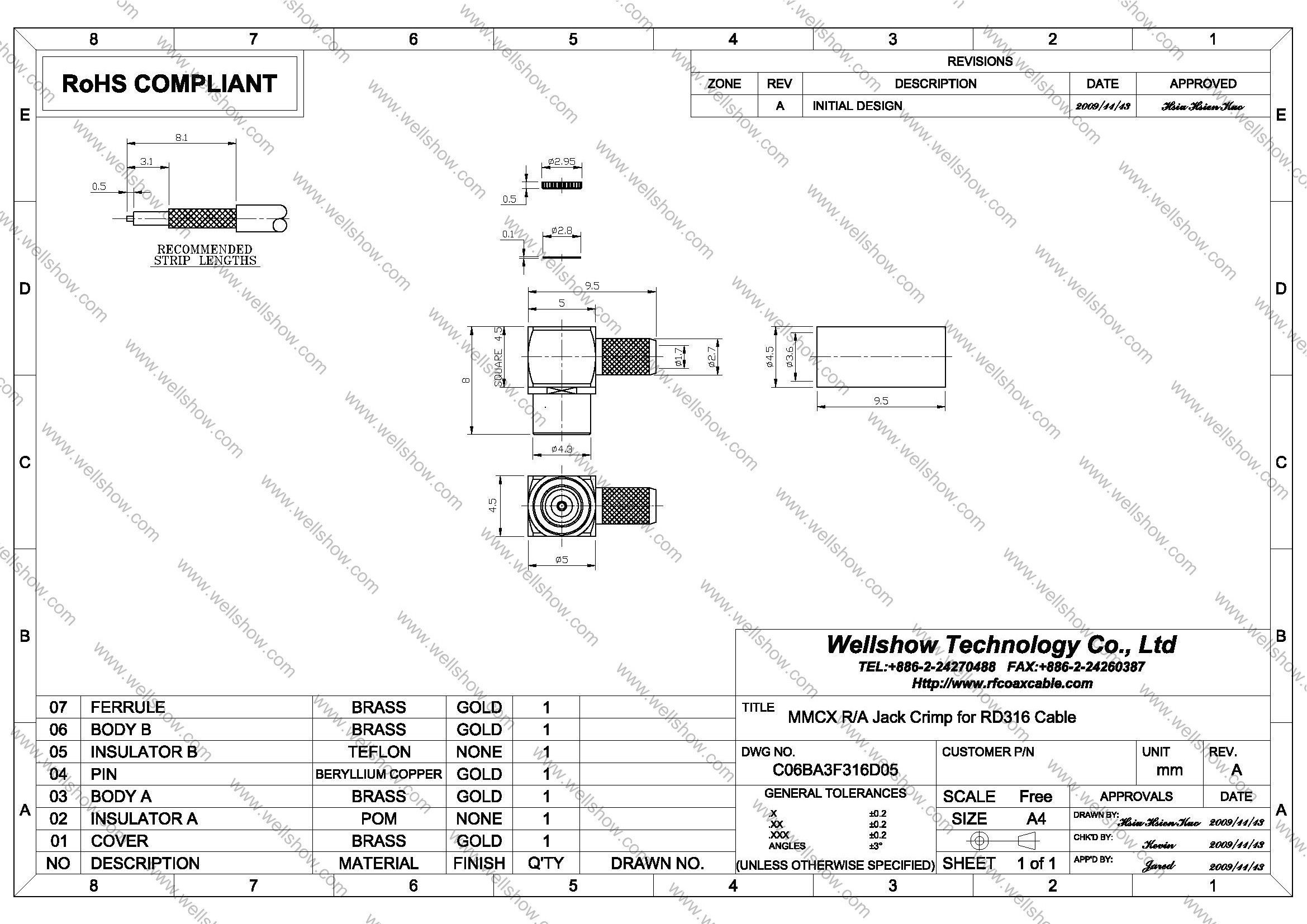
MMCX is the popular RF connectors. This MMCX connector is jack/ female, and right angle/ RA type. It’s terminated with RF Coaxial Cable by crimping to be MMCX adaptor RF cable. The applicable RF coax cable is RG174/ RG316/ RG188/ LMR100/ RD316 RF coaxial cable. Its plating is Gold, with 50 ohm.
MMCX connector is small size in RF connector. MMCX Connector has been designed to be snap-on mating. Besides, MMCX jack crimp series still have straight crimp jack, straight bulkhead crimp jack, PCB mount jack, edge mount jack and SMT jack . MMCX Connector commonly is used for 0~3GHz. If you need customized RF connector, or RF cables, even any special needs, please contact us to get the best service.
MMCX connector jack right angle/ RA crimp type can be terminated with RG174/ RG316/ RG188/ LMR100/ RD316 RF coaxial Cable to be RF Cable assembly. Quick mating, light weight and high performance are reasons to be popularly used in various Radio Frequency applications. MMCX RF connector is most commonly used in GPS Antenna, GSM Antenna or GPS/GSM application these kinds of RF connectors industry.
Part Numbers
| P/N | RF connector description | Cable Group | Ohm |
| C06BA3F174005 C06BA3F316D05 | MMCX RF connector R/A crimp jack MMCX RF connector R/A crimp jack | RG174, RG316, RG188, LMR100 RG316D(RD316) | 50 50 |
Cable Assembly
Cable assembly Instructions Crimp type


Step6. Slide the ferrule over the shielding, and proceed the first open-short test to make sure signal can transmit well.
Step7. Crimp the ferrule to let it become tighter.


Step10. Do the open-short test of every cable assembly before QC examination.
Specification
| Electrical | |
| Impedance | 50 ohm |
| Frequency range | 0 ~ 6 GHz |
| VSWR | Straight type ≤ 1.3 max. |
| R/A type ≤ 1.5 max. | |
| Dielectric withstanding voltage | 500 V rms |
| Working voltage0 | 170 V rms |
| Center contact resistance | ≤ 5.0 mΩ (Milliohms max.) |
| Outer contact resistance | ≤ 2.5 mΩ (Milliohms max.) |
| Insulation resistance | ≥ 103 MΩ (Megohms min.) |
| Mechanical | |
| Coupling | Lock-snap |
| Contact Retention | 2.3 lbs min. |
| Mating Durability | 500 cycles min. (For Beryllium copper contact only) |
| Environmental | |
| Temperature Range | Teflon −65ºC ~ +155 ºC |
| Vibration | MIL-STD-202 Meth. 204 |
| Corrosion resistance | MIL-STD-202 Meth. 101 |
| Materials | |
| Body, coupling nut | Brass |
| Insulator | Teflon |
| Center contact | Brass for male, |
| Beryllium copper for female | |
| Crimping sleeve | Annealed Brass |
| Body plating | Gold (Ag) |
| Center contact plating | Gold (Ag) |
Note: These characteristics are typical and may not apply to all connectors.


