
Information
MMCX RF connectors
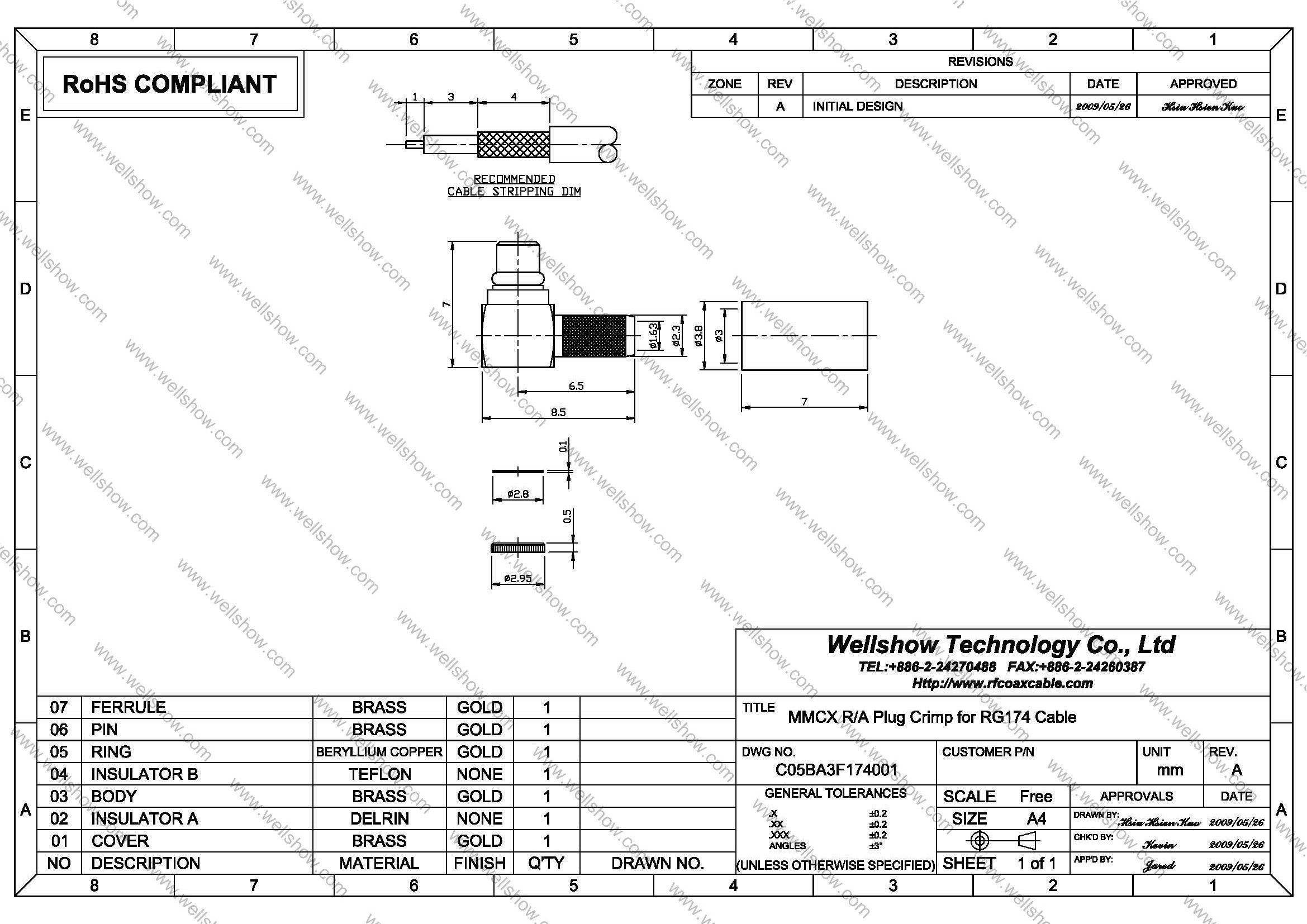
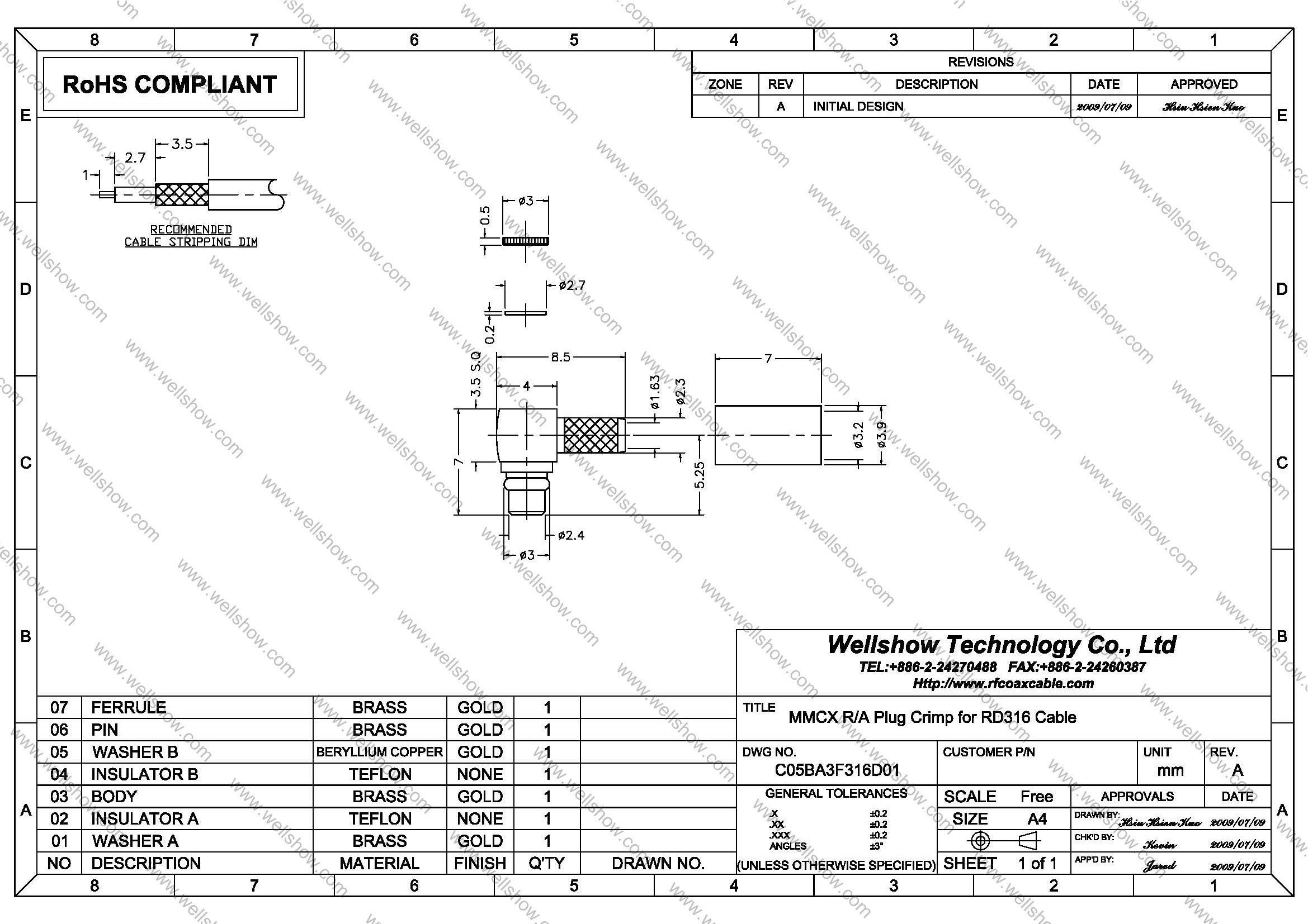
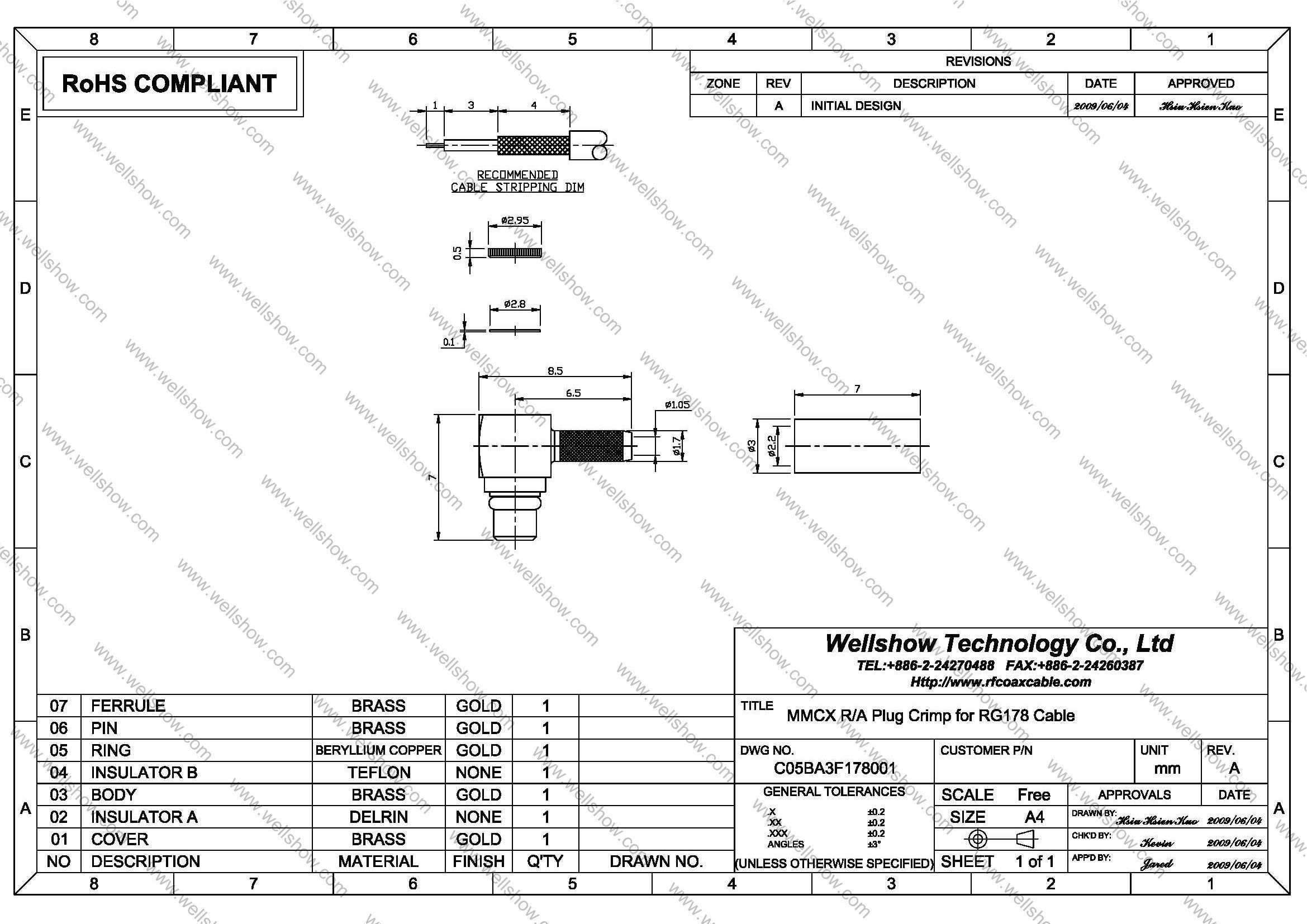
MMCX connector is one kind of RF connectors. This MMCX connector is plug/ male and right angle/ RA type. This cable connector is used to terminate with RF Coax Cable like RG174/ RG316/ RG178/ 1.13mm/ 1.48mm/ 1.37mm/ 1.32mm/ RG196/ RG188 by crimping to be MMCX connector cables. Its body plating is gold and its impendence is 50 ohm.
MMCX connector belongs to small size in RF connector. MMCX Connector’s mating is snap-on type. Besides, MMCX plug/ male crimp series have straight and right angle outlook. MMCX Connector commonly is used for 0~3GHz. If you have any special request about RF connector & RF cable, we are welcome OEM or customized products.
MMCX connector plug right angle/ RA crimp type can be terminated with RG174/ RG316/ RG178/ 1.13mm/ 1.48mm/ 1.37mm/ 1.32mm/ RG196/ RG188 RF coaxial Cable to be RF Cable assembly and transmit RF Signal well in telecommunications. MMCX RF connector is most commonly used in GPS/GSM Antenna (internal or external) or WLAN or 3G these kinds of RF connectors industries.
Part Numbers
| P/N | RF connector description | Cable Group | Ohm |
| C05BA3F174001 C05BA3F316D01 C05BA3F178001 C05BA3F132001 C05BA3F113001 | MMCX RF connector R/A crimp plug MMCX RF connector R/A crimp plug MMCX RF connector R/A crimp plug MMCX RF connector R/A crimp plug MMCX RF connector R/A crimp plug | RG174, RG316, RG188, LMR100 RG316D(RD316) RG178, RG196 1.32 1.13 | 50 50 50 50 50 |
Cable Assembly
Cable assembly Instructions Crimp type

Step1. All parts of MMCX connector are shown as the top line.

Step2. Strip the Coaxial Cable into center conductor, insulator, shielding three parts per recommended stripping dimension shown in connector spec.

Step3. Tin the center conductor if the dimension of the cable is from 1.13mm to 1.48mm. This process can help soldering more easily.

Step4. Slide the ferrule onto the cable jacket.

Step5. Insert the center conductor into the pin’s slot and solder it, and then spread out the shielding onto the knurled part.
Step6. Slide the ferrule over the shielding, and proceed the first open-short test to make sure signal can transmit well.
Step7. Crimp the ferrule to let it become tighter.

Step8. Put the insulator and cap on and press them into main body.

Step9. Wear the heat shrink onto the ferrule and then shrink it.
Step10. Do the open-short test of every cable assembly before QC examination.
Specification
MMCX Connector Specification
| Electrical | |
| Impedance | 50 ohm |
| Frequency range | 0 ~ 6 GHz |
| VSWR | Straight type ≤ 1.3 max. |
| R/A type ≤ 1.5 max. | |
| Dielectric withstanding voltage | 500 V rms |
| Working voltage0 | 170 V rms |
| Center contact resistance | ≤ 5.0 mΩ (Milliohms max.) |
| Outer contact resistance | ≤ 2.5 mΩ (Milliohms max.) |
| Insulation resistance | ≥ 103 MΩ (Megohms min.) |
| Mechanical | |
| Coupling | Lock-snap |
| Contact Retention | 2.3 lbs min. |
| Mating Durability | 500 cycles min. (For Beryllium copper contact only) |
| Environmental | |
| Temperature Range | Teflon −65ºC ~ +155 ºC |
| Vibration | MIL-STD-202 Meth. 204 |
| Corrosion resistance | MIL-STD-202 Meth. 101 |
| Materials | |
| Body, coupling nut | Brass |
| Insulator | Teflon |
| Center contact | Brass for male, |
| Beryllium copper for female | |
| Crimping sleeve | Annealed Brass |
| Body plating | Gold (Ag) |
| Center contact plating | Gold (Ag) |
Note: These characteristics are typical and may not apply to all connectors.


