
Information
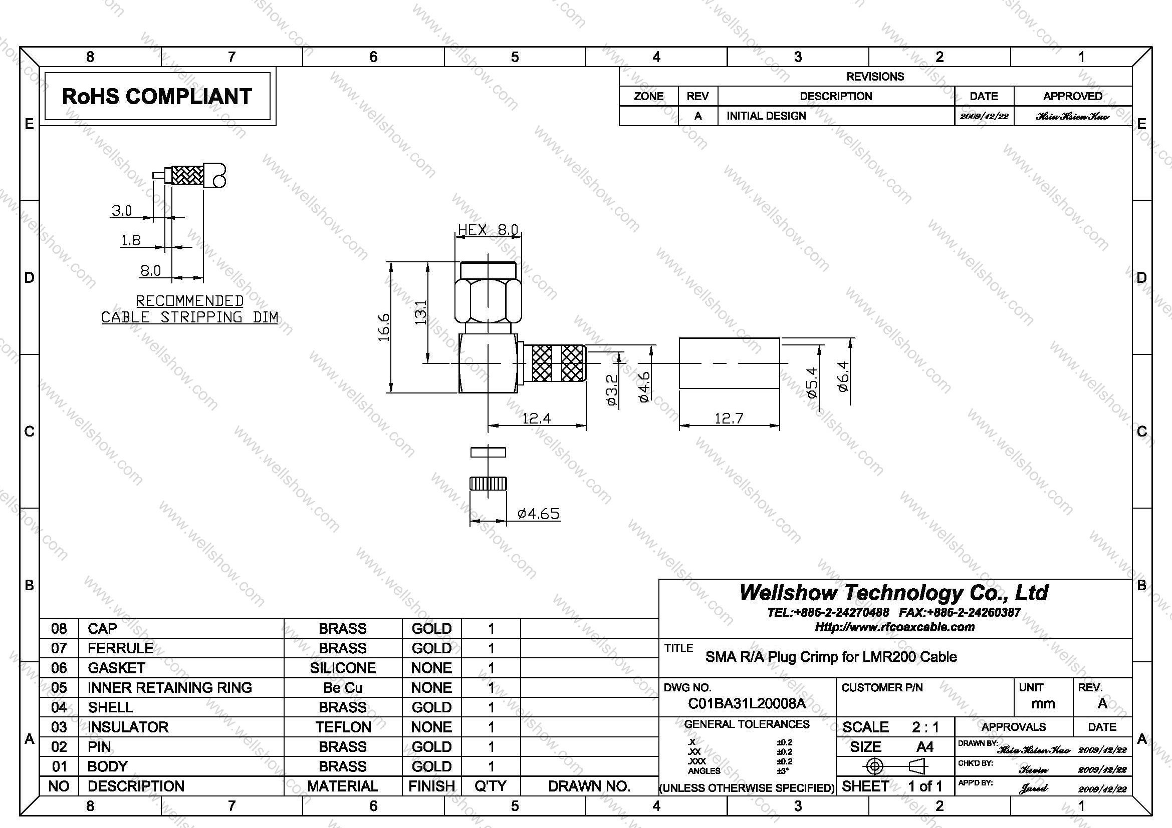
This male SMA connector is a cable connector which is designed to terminate with thicker coaxial cables. The biggest coaxial cable this right angle type SMA connector can terminate is LMR200 which has 5.0mm diameter.
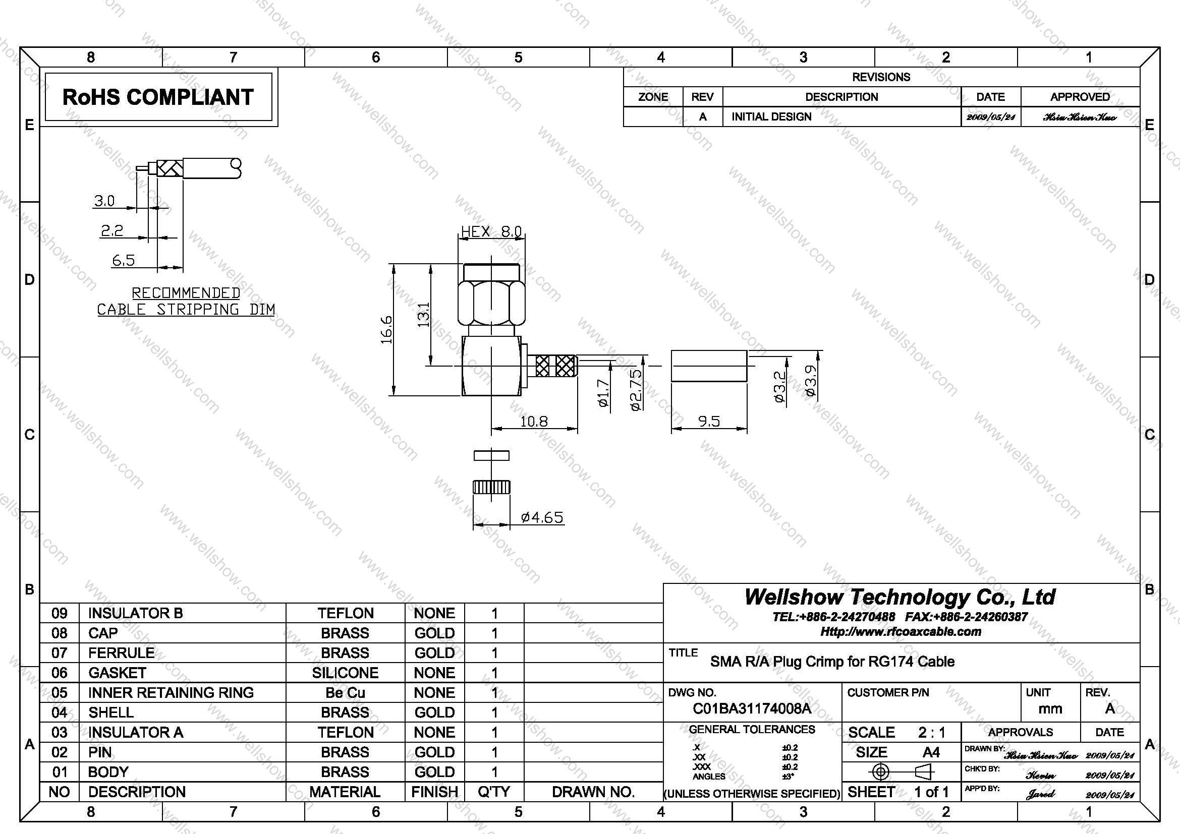
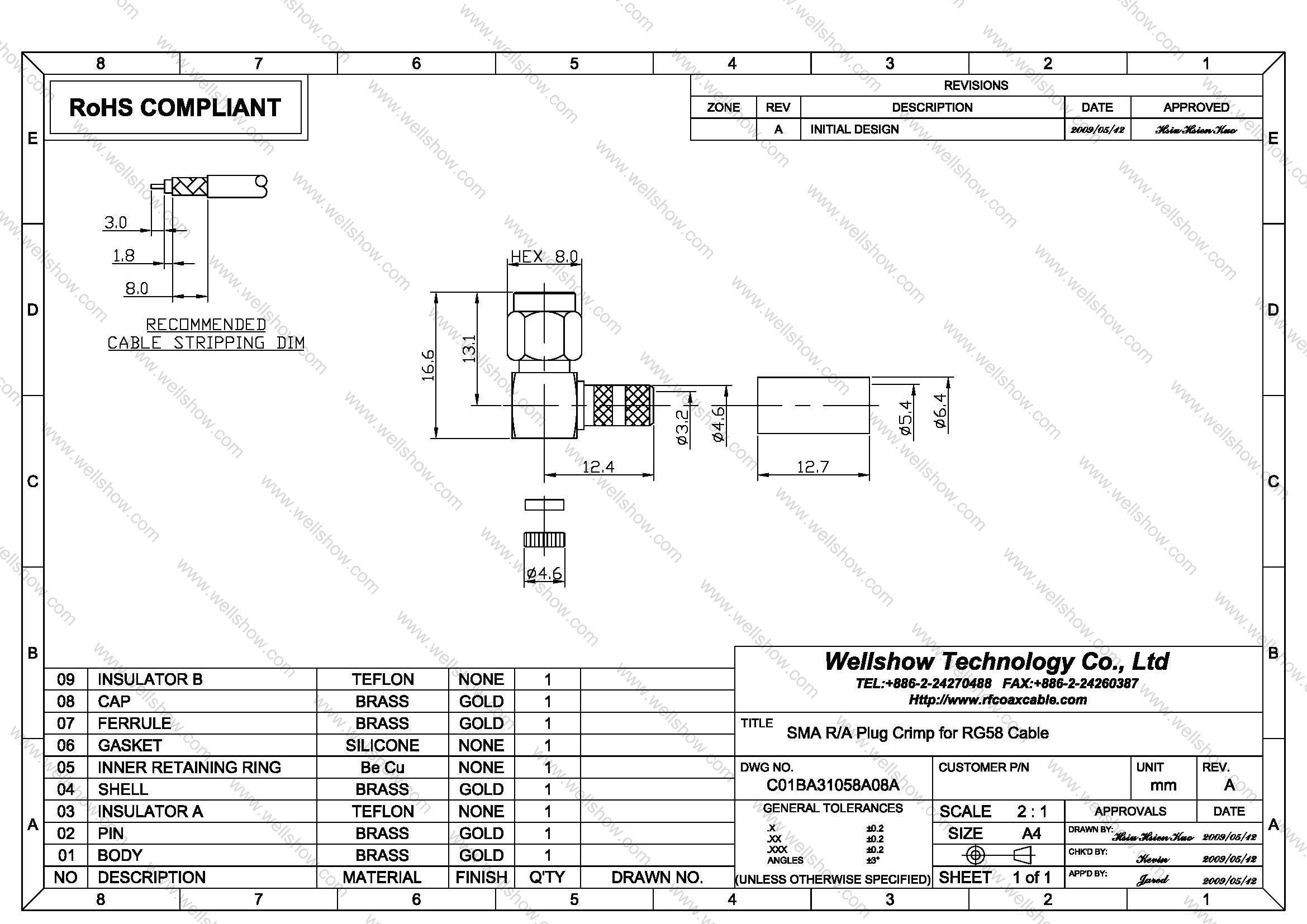
All kinds of RF coaxial cable for SMA male Right Angle crimp type are RG174, RG316, RG58, RG223, LMR240, LMR195, LMR200, RG188, LMR100, RG142, RG400, RG141, RG303, RG55, B7806A, B7807A, RG8X, Belden 8214.
The SMA adaptor cable/ SMA connectors cable/ SMA cable assembly are used in various RF market, like GPS antenna, GSM antenna, WLAN and so on. Wellshow not only can provide you SMA right angle gold plug, but also SMA right angle nickel type. If you want to cost down, SMA connector right angle nickel plug will be your best option.
SMA connector is an acronym for SubMiniature version A and was developed in the 1960’s. Built in accordance with MIL-C-39012 and CECC 22110/111, SMA connectors are designed per SMA interface dimensions.
If you need Right Angle male SMA connector for mini coaxial cable like 0.81, 1.13, 1.32, 1.37, 1.48 or RG178, please link here.
Part Numbers
| P/N & Drawing | Description | Cable Group | Ohm |
|---|---|---|---|
| C01BA31174008A C01BA31316D08A C01BA31058A08A C01BA31400008A C01BA31223008A C01BA31L20008A | SMA right angle crimp plug SMA right angle crimp plug SMA right angle crimp plug SMA right angle crimp plug SMA right angle crimp plug SMA right angle crimp plug | RG174, RG316, RG188, LMR100 RG316DS (double shielding) RG58, RG141, RG303, LMR195, B7806A RG142, RG400, RG55 RG223 LMR200, B7807A | 50 50 50 50 50 50 |
Cable Assembly
Cable assembly Instructions Crimp type
Step1. All parts of SMA RF connector are shown as the top line.
Step2. Strip the RF coaxial cable into center conductor, insulator, shielding three parts per recommended stripping dimension shown in SMA RF connector spec.
Step3. Slide the heat shirking tube then ferrule onto the cable jacket.
Step4. Insert the center conductor of cable into the pin’s slot and solder it, and then spread out the shielding onto the knurled barrel.
Step5. Slide the ferrule over the shielding, and proceed the first open-short test to make sure signal can transmit well.
Step6. Crimp the ferrule.
Step7. Place the insulator then cap on, and press cap into main body.
Step8. Heat shrink t the shrinking tube.
Step9. Do the open-short test of every cable assembly before QC examination.
Specification
SMA Connector Technical Characteristics
| Electrical | |
| Impedance | 50 ohm |
| Frequency range | 0 ~ 18 GHz |
| VSWR | Straight type ≤ 1.3 max. |
| R/A type ≤ 1.5 max. | |
| Dielectric withstanding voltage | 1000 V rms min. for RG142, RG405 750 V rms min. for RG316, RG402 500 V rms min. for RG178 |
| Working voltage | 500 V rms max. for RG142, RG405 375 V rms max. for RG316, RG402 170 V rms max. for RG178 |
| Center contact resistance | ≤ 6.0 mΩ (Milliohms max.) |
| Outer contact resistance | ≤ 2.0 mΩ (Milliohms max.) |
| Insulation resistance | ≥ 5×10³ MΩ (Megohms min.) |
| Mechanical | |
| Coupling | 1/4-36 thread |
| Contact Retention | 15 in-lbs. min. |
| Mating torque | 2 in-lbs. min. |
| Mating Durability | 500 cycles min. (For Beryllium copper contact only) |
| Environmental | |
| Temperature Range | −65ºC ~ +155 ºC |
| Vibration | MIL-STD-202 Meth. 204 |
| Corrosion resistance | MIL-STD-202 Meth. 101 |
| Materials | |
| Body, coupling nut | Brass, Non-magnetic stainless steel |
| Insulator | Teflon |
| Center contact | Brass for male, Beryllium copper for female |
| Crimping sleeve | Annealed Brass |
| Body plating | Nickel (Ni), Gold (Au), Passivated |
| Center contact plating | Gold (Au) |
Note: These characteristics are typical and may not apply to all connectors.


