
Information
SMA coax connector is a precision coaxial connector for microwave applications. SMA RF connectors have a thread interface and 50 ohm dependence just like N, FME, SMA, SMC RF connectors and so on. It can be crimped with RF coaxial cable from 0.81mm, 1.13mm, 1.32mm, 1.37mm, 1.48mm, to RG178.
SMA connector has complete and full production line than other RF cable connectors. SMA connector is a mature RF connector and has big demands.
Besides SMA straight crimp plug, we still have SMA right angle crimp plug. Various RF SMA connectors are widely used in Telecommunication, Vehicle Tracking System, Wireless LAN and so on.
Part Numbers
| P/N & Drawing | Description | Cable Group | Ohm |
|---|---|---|---|
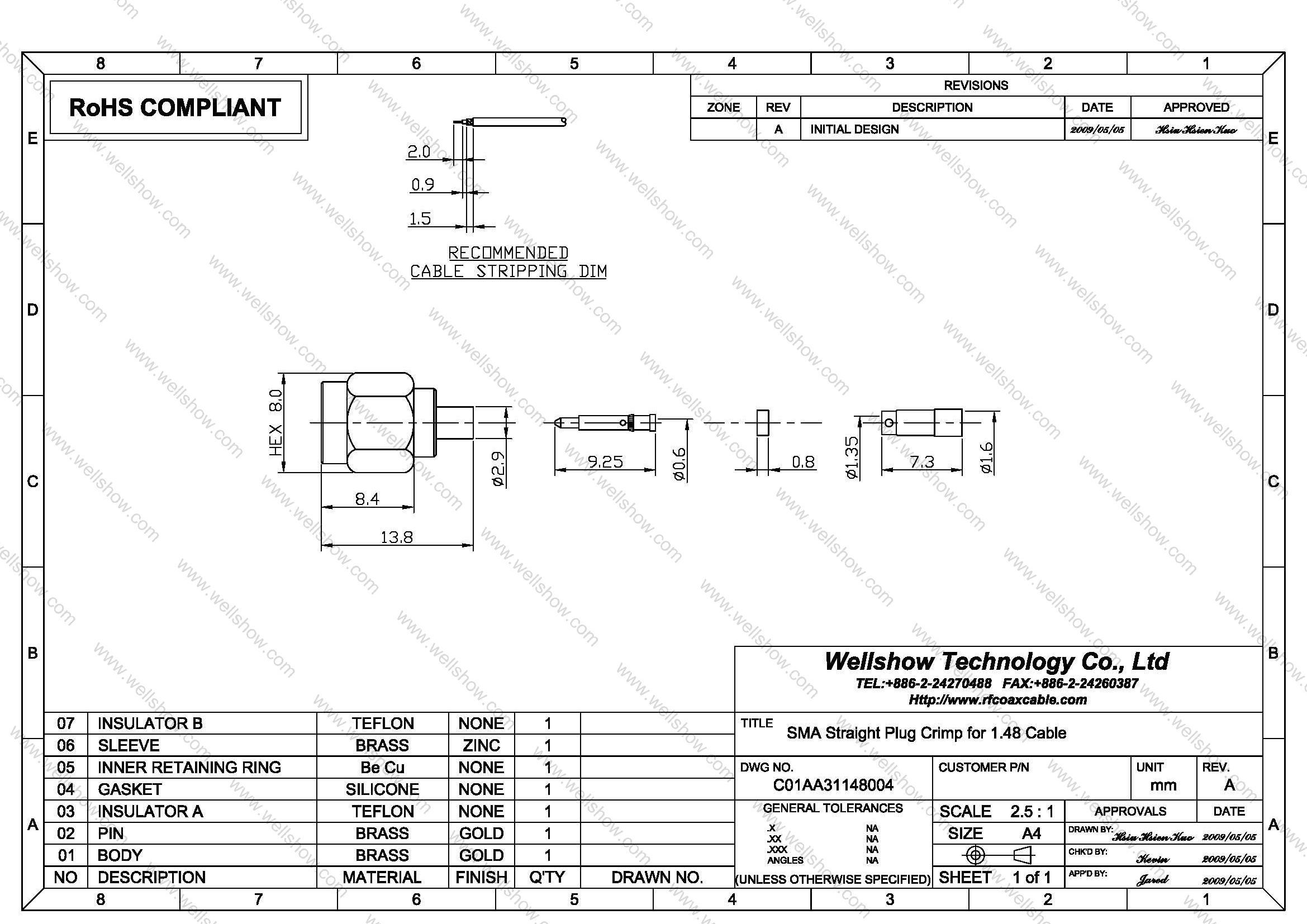
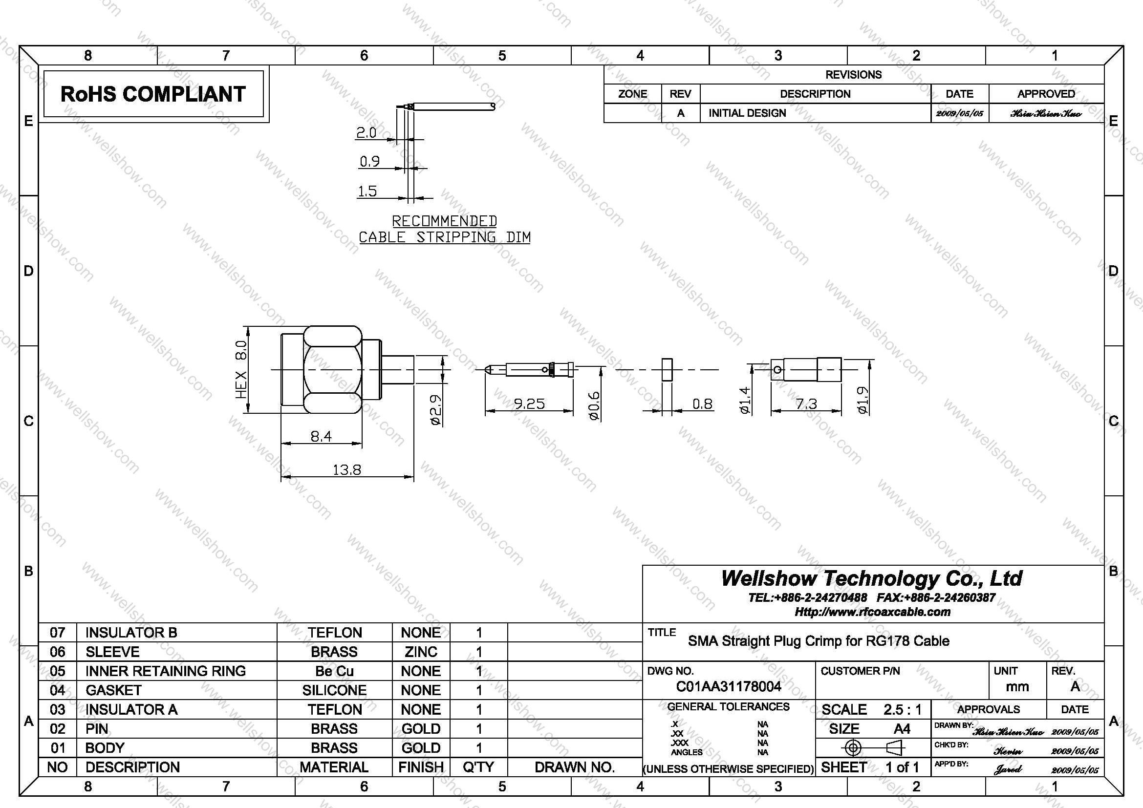
| C01AA31081004 C01AA31113004 C01AA31132004 C01AA31137004 C01AA31148004 C01AA31178004 | SMA straight crimp plug SMA straight crimp plug SMA straight crimp plug SMA straight crimp plug SMA straight crimp plug SMA straight crimp plug | 0.81mm 1.13mm 1.32mm 1.37mm 1.48mm RG178 | 50 50 50 50 50 50 |
Cable Assembly
Cable assembly Instructions Crimp type
Step1. All parts of SMA RF connector are shown as the top line.
Step2. Strip the RF coaxial cable into center conductor, insulator, shielding three parts per recommended stripping dimension shown in SMA RF connector spec.
Step3. Slide the heat shrinking tube, then ferrule onto the cable jacket.
Step4. Insert the center conductor of the cable into the contact pin of SMA plug and then solder through the side hole.
Step5. Spread out the shielding and put the contact pin into main body until it stops, and then cover shielding onto the knurled barrel.
Step6. Slide the ferrule over the shielding, and proceed the first open-short test to make sure signal can transmit well.
Step7. Crimp the ferrule.
Step8. Heat shrink the shirking tube.
Step9. Do the open-short test of every cable assembly before QC examination.
Specification
SMA Connector Technical Characteristics
| Electrical | |
| Impedance | 50 ohm |
| Frequency range | 0 ~ 18 GHz |
| VSWR | Straight type ≤ 1.3 max. |
| R/A type ≤ 1.5 max. | |
| Dielectric withstanding voltage | 1000 V rms min. for RG142, RG405 750 V rms min. for RG316, RG402 500 V rms min. for RG178 |
| Working voltage | 500 V rms max. for RG142, RG405 375 V rms max. for RG316, RG402 170 V rms max. for RG178 |
| Center contact resistance | ≤ 6.0 mΩ (Milliohms max.) |
| Outer contact resistance | ≤ 2.0 mΩ (Milliohms max.) |
| Insulation resistance | ≥ 5×10³ MΩ (Megohms min.) |
| Mechanical | |
| Coupling | 1/4-36 thread |
| Contact Retention | 15 in-lbs. min. |
| Mating torque | 2 in-lbs. min. |
| Mating Durability | 500 cycles min. (For Beryllium copper contact only) |
| Environmental | |
| Temperature Range | −65ºC ~ +155 ºC |
| Vibration | MIL-STD-202 Meth. 204 |
| Corrosion resistance | MIL-STD-202 Meth. 101 |
| Materials | |
| Body, coupling nut | Brass, Non-magnetic stainless steel |
| Insulator | Teflon |
| Center contact | Brass for male, Beryllium copper for female |
| Crimping sleeve | Annealed Brass |
| Body plating | Nickel (Ni), Gold (Au), Passivated |
| Center contact plating | Gold (Au) |
Note: These characteristics are typical and may not apply to all connectors.


